
Hazen Williams
The Original Hazen-Williams formula was published in 1920 in the form:
V=C1r
0.63 s0.54 0.001-0.04
where
C1 = Hazen-Williams roughness coeificient
r = hydraulic radius (ft)
s = hydraulic gradient
The variations inherent with diameter changes are accounted for by the
introduction of the coefficient C2 so that
Q = 4.03 x 10⁻⁵ D2.65 H0.54
where
Q = discharge (litres/second)
D = internal diameter (mm)
H = head loss (meters/100 meters length of pipe)
Head Loss in Fittings
Wherever a change to pipe cross section, or a change in the direction of flow occurs in a pipeline, energy is lost and this must be accounted for in the hydraulic designs. Under normal circumstances involving long pipelines these head losses are smaill in relation to the head losses due to pipe wall friction. However, installations where a large number o fitings are included in the design.
The general relationship for head losses in fittings may be expressed as:
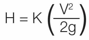
where
H = Head loss (m)
V = Velocity of flow (m/s)
K = head loss coefficeint
g = gravitational acceleration (9:81 m/s2)
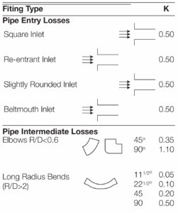
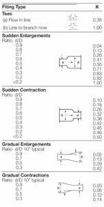
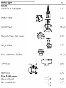
The value of the head loss coefficient K is dependet on the particular geometry of each fitting, and values for specific cases are listed in the Table below. The total head loss in the pipeline network is then obtained by adding together the calculations performed for each fitting in the system, the head loss in thepipes, and any other design head losses.
JOINTING
One of the greatest features of HDPE pipes is the fact that a wide variety of jointing systems is available to suit a whole range of applications. The jointing systems can be divided into permanent jointing and detachable jointing. The schematic below illustrates the available systems.
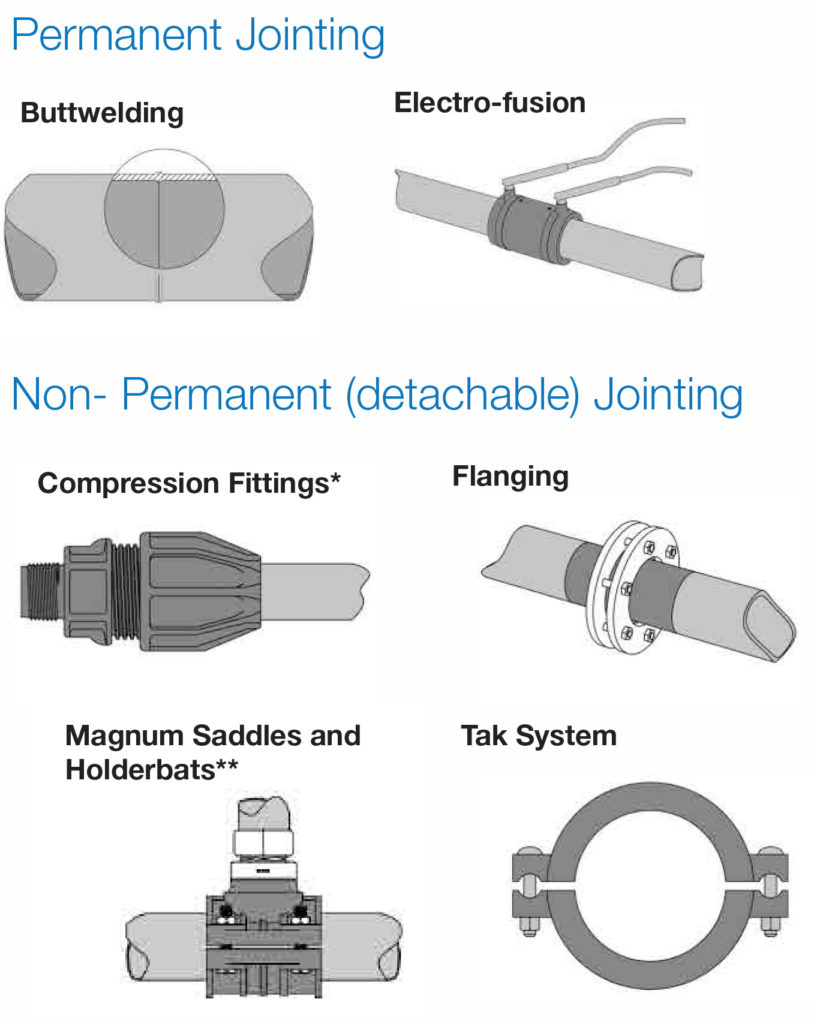
BUTT FUSION
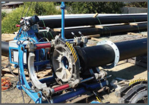
Butt fusion is gnerally applied to PE pipes within the size range 90 mm to 1000 mm for joints on pipes, fittings, and end treatments. Butt fusion provides a homogeneous joint with the same properties as the pipe and fittings materials, and ability to resist longitudinal loads.
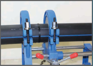
Butt fusion machines need to be sufficiently robust to align and pressuries the pipe ends within close tolerances, and to rpovide heating and pressuristation of the jointing surfaces within required parameter tolerance.
T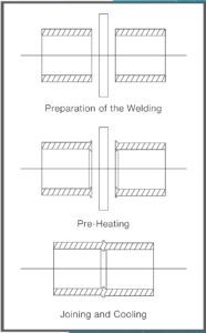 he but fusion process consists of the following steps which are shown in principle in the Figure
1. The pipe must be installed in the wlding machine and the ends cleanded with non deposiitng alcohol to remove all dirt, dust, moisture and greasy films from a zone approximiately 75 mm from the end of each pipe, on both inside and outside diameter faces.
2. The ends of the pipes are trimmed using a rotating cutter to remove all rough ends and oxidation layers. The trimmed end faces must be square and parallel.
3. The ends of the PE pipes are headted by concat under pressure against a heater plate. The heater plates must be clean and free from contamination and maintained within a surface temperature range of 190o C to 225o C (depending on the size of the pipe). Contact is maintained until even heating is established around the pipe ends,
and the contact pressure then reduced to a lower value called the heat soak pressure. Contact is then maintained until the appropriate heat soak time elapses.
4. The heated pipe ends are then retracted and the heater plate removed. The heated PE pipe ends are then brought together and pressurised evenly to the welding pressure value. This pressure is maintained for a period to allow the welding process to take place, and the fused joint to cool down to ambient temperture and hence develop full joint strength. The pressure adopted in this phase should be in the range 0.15MPa to 0.18MPa on the ends of the pipes.
During this cooling period the joints must remain undisturbed and under compression, Under no circumstances should the joints be sprayed with cold water.
The combinations of times, temperture, and pressures to be adopted depends on, the diameter and wall thickness of the pieps.
The final weld beads should be fully rolled over, free from pitting and voids, correctly sized, and free from discoloration.
 Post-Welding Checks:
- Use bead gauge to check that bead width meets specification.
- Check repeatability of weld beads along pipe string.
- Externally debead the weld and inspect for slit defects.
- Check for surface dirt on removed bead.
The Rules For Butt Fusion:
NEVER
- Attempt to weld together pipes of different SDR (wall thickness).
- Touch trimmed pipe ends.
- Leave trimming swarf inside pipe or on welding machine.
- Allow equipment to get wet or dusty.
- Use non-approved machinery.
- Remove a weld from the machine before cooling time has elapsed.
- Allow untrained personnel to use welding equipment.
- Cut corners in any part of the welding procedure.
- Weld pipes of different material.
 ALWAYS
- Support pipes on rollers.
- Check pipe and welding clamps are clean.
- Check for thoroughness of pipe trimming.
- Check for alignment of pipe ends.
- Measure the drag pressure for each weld.
- Cover pipe ends to prevent draughts.
- Use a welding tent.
- Check that pipe wall thickness match before butt welding.
- Stand well clear of automatic machines during operation.
- Carry out a dummy weld at the start of a welding session.
Pre-Welding Checks:
Before commencing a welding operation, check that:
- The site is suitable for welding and a tent is used.
- You know the correct welding parameters for the machine and pipe being welded. These are normally on the machine’s data plate. If in doubt, refer to our Technical Services Department.
- The machine is complete and undamaged.
- The generator has enough fuel for the work to be done.
- The heater plate is clean – if not, was it while cold with lots of clean water and dry with a clean, lint free cloth or paper towel.
- The trimming tool is clean and sharp.
- The clamp shells are of correct size and clean, with no embedded grit which could lead to pipe misalignment.
- The heater plate is at the correct temperature.
- The pipes to be welded are of the same material and SDR (wall thickness).
Dummy Welds:
Before a welding session, a dummy weld should be carried out to clean the heater plate. The welding process (see instructions below for manual and automatic) should be followed up to the heat-soak stage, at which point the weld may be aborted. Any dirt will be transferred from the heater plate to the pipe end which, when cold can be re-trimmed for welding.
Pipes larger than 180mm should be dummy welded twice before proceeding